Project Overview
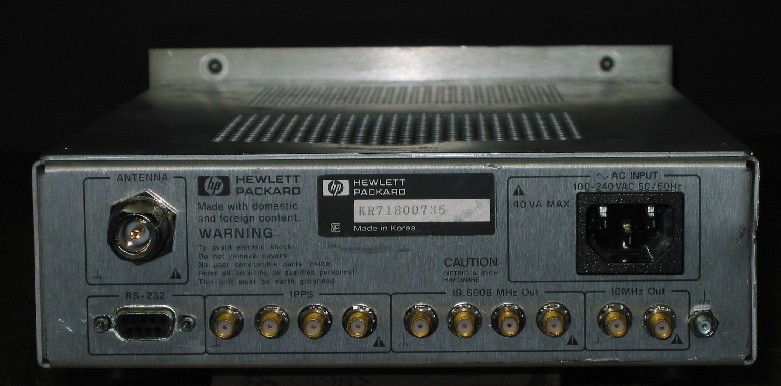
The HP Z3816A provides high accuracy frequency and time outputs that can be used for a variety of purposes. By disciplining the internal oscillator with a satellite receiver, the Z3816A provides 10MHz,19.6608 MHz and 1 PPS outputs (synchronized by GPS to UTC) via connections on the rear panel (For more information on the HP Z3816 and the similar HP Z3801A see Bill Jones' website (www.realhamradio.com).In order to obtain the time or modify parameters, a connection is required to a PC or external terminal device via an RS232 serial interface. PC programs (see HP Sat Stat, gps.exe) are available that handle the communications with the Z3816A and provide an easy to use interactive display on a standard windows PC. However, this requires a dedicated PC connected to the Z3816A if continuous time output is desired.
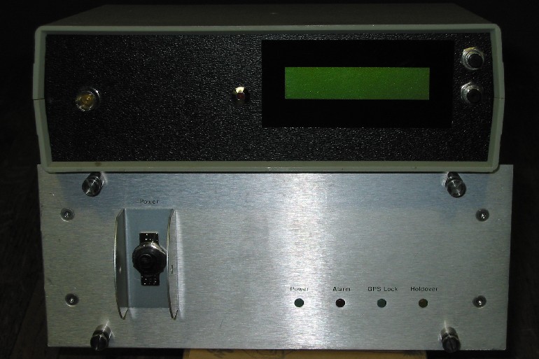
In the article below, I describe a project I recently completed that replaces the PC with a small, inexpensive, easy to assemble and use, microprocessor based unit that provides a continuously updated time display and allows the user to enter HP Z3816A or Z3801A commands directly via a extendable simple user interface.
The Z3816A Auxiliary Display Unit (ADU) is built around a Parallax BS2 sx Stamp microprocessor (www.parallaxinc.com), a Scott Edwards (www.seetron.com) two-line by sixteen character display, a Maxim 233A RS232 interface IC (www.maxim-ic.com) and other miscellaneous hardware. A Stamp BASIC application provides the software interface between the ADU and the Z3816A. The project is described below:
Hardware Overview:
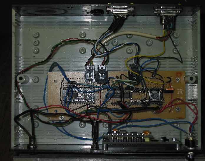
I chose the Parallax BS2 sx microprocessor from Parallax since it is easy to program, is reasonably inexpensive, and I used it for other similar projects in the past. The project will function equally well with the standard BS2 microprocessor, with no logic or programming changes (the timing constants used for output to the Z3816A and LCD display must be modified, however these values are included in the program). All components are standard off-the-shelf electronics, and the total for the project is between $75 and $100 depending on the microprocessor and LCD characteristics. The entire project is housed in a plastic case slightly smaller than the Z3816A.Circuit Design
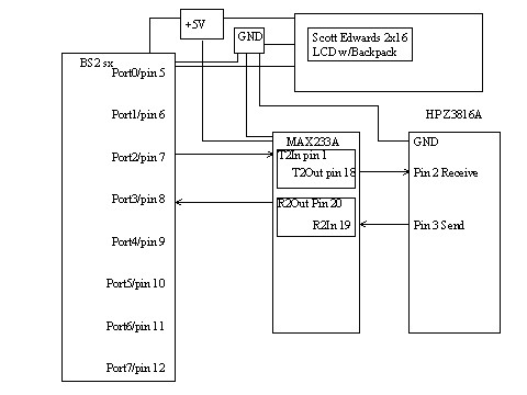
The BS2 sx is powered from a standard +5 volt 1 amp voltage regulator, which is connected to an external 9-volt wall-wart DC transformer. Using an external +5 volt regulator bypasses the low current on-board voltage regulator supplied with the BS2 sx and provides additional current for future expansion.Because the BS2 sx serial input and output ports operate at TTL levels, and the HP Z3816A operates at true RS232 voltages, an external interface is required for voltage translation between the two devices. For this interface I used the Maxim 233A which handles two TTL and two RS232 devices, and requires no external components to operate. The Maxim 233A accepts TTL inputs on the transmit line from the BS2 sx and converts these TTL signals to RS232 levels for the Z3816A. It also receives RS232 levels from the Z3816A and converts them to TTL levels for the BS2 sx.
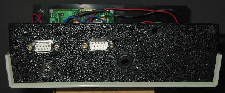
For this application, the BS2 sx transmits on output port 2 (pin 7) using the Z3816A communication default parameters (9600 baud, no parity, 8 bit data, 1 stop bit) and receives on input port 3. The BS2 sx and Z3816A is connected to channel 2 of the Maxim 233A (channel 1 is unused). The BS2 sx Port 2 is connected to T2IN (pin 1) on the MAX233A. This channel corresponds to Pin 18 (T2OUT) on the MAX233A. Pin 18 on the MAX233A connects to the receive pin 2 on the Z3816A (9 pin RS232 D-Shell Connector). The response from the Z3816A is sent on pin 3 of the RS232 connector, which connects to pin 19 (R2IN) that corresponds to pin 20 (R2OUT) on the MAX233A. Pin 20 from the MAX233A is then connected to Input Port 3 (pin 8) on the BS2 sx. Note that for the MAX233A to operate properly the following pins must be connected: pin 12 to pin 17; pin 11 to pin15; and pin 10 to pin 16. Specifications for the MAX233A can be found at: http://pdfserv.maxim-ic.com/arpdf/MAX220-MAX249.pdf
The LED panel is used to display the local or UTC time, and the time zone offset from UTC. The LED display panel used is the Scott Edwards Electronics BPI-216 Supertwist 2x16 LCD with Backpack-Protocol Serial Interface. The Backpack-Protocol Serial Interface allows a three-wire (+5v, serial data, and ground) connection between the BS2 sx and the display. Specifications for the display can be found at: http://www.seetron.com/pdf/bpi_bpk.pdf. Output to the display is via serial output port zero on the BS2 sx (pin 5). Output to the display is via serial output port zero on the BS2 sx (pin 5).
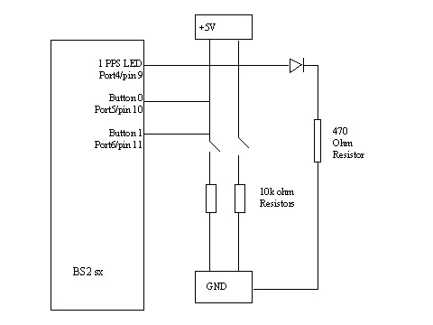
There are two momentary push buttons connected to the BS2 sx on input ports 5 and 6 (pins 10 and 11). These are active high switches connected from +5v through 10k ohm resistors to ground. During program execution, the BS2 sx reads the and branches to a program location based on the state of the switch (press on not-pressed) at the time the button instruction executes. Button-One, connected to input port 6 (Stamp pin 11) is used to change states from the "Display Time State" to "Command Input State" and back. Button-Two, connected to BS2 sx input port 5 (Stamp pin 10) is used to scroll through the various time zones (from 0 to 23).
The final hardware component is a single red LED located on the front panel. This LED flashes once per second, and is synchronized to the beginning of each second. Since the LED is under program control, the flash is delayed by the execution time of the program, which checks for the second change in software before turning on the LED. The LED is connected to output port 4 (Stamp pin 9) and is on for 100 milliseconds each second. The LED connects to ground through a 470-ohm resistor.